

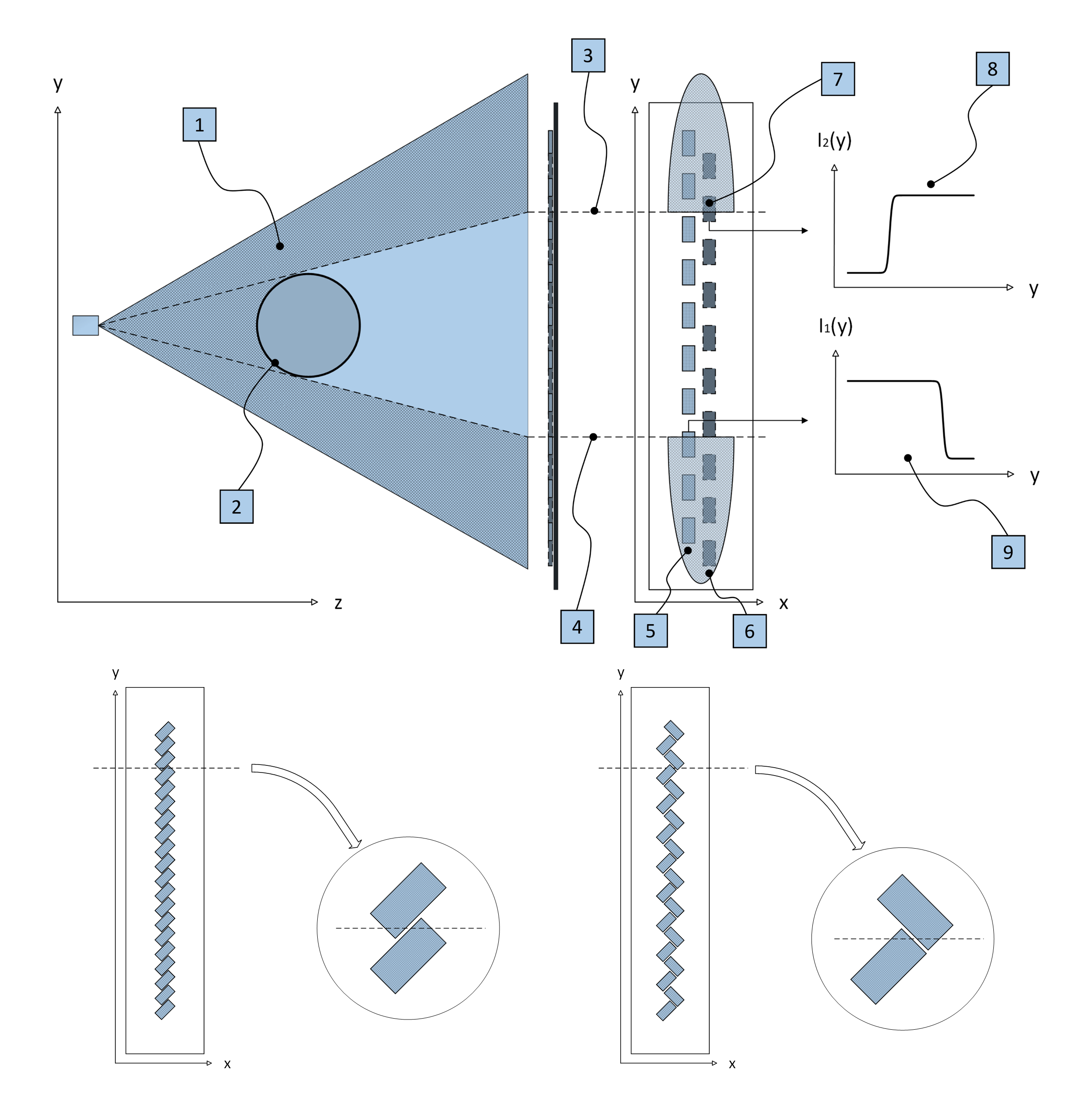
Patent DE102023110189A1 describes a non-contact optical method for determining the radius or diameter of a nearly rotationally symmetrical component. The system uses a divergent light beam and a specially arranged line detector to record the enlarged shadow of the component during production.
The method was developed for applications in which manual contact measurements are too slow, inaccurate, or harmful to the component surface. One important example is the continuous measurement of composite components during the filament winding process.
What problem does the patent address?
Rotationally symmetrical composite components often grow layer by layer during production. Therefore, manufacturers must measure the increasing diameter regularly and compare it with the specified tolerance.
In filament winding, a machine applies resin-impregnated fibre tapes to a rotating winding tool. Depending on the application, these tapes may contain glass fibres, carbon fibres, basalt fibres, aramid fibres, natural fibres, or combinations of different materials. Several layers form a laminate whose final dimensions influence both installation compatibility and mechanical properties.
The patent description states that typical permitted deviations of the final diameter can range from approximately ±0.2 mm to ±1.5 mm. The required measurement accuracy may therefore need to reach about ±0.05 mm. The measured diameter also allows manufacturers to calculate the developing wall thickness and individual layer thickness.
Limitations of manual diameter measurement
Conventional filament-winding processes often use a circumference tape or calliper to measure the component manually. An operator must stop the machine, place the measuring device against the wet laminate, read the value and record the result.
This procedure creates several potential sources of error:
- varying contact force,
- compression of the wet laminate,
- parallax during reading,
- contamination of the measuring tool by resin,
- differences between operators,
- changing surface properties,
- interruptions to the production process.
In particular, a tape measure or calliper can compress the still-soft component. Consequently, the measurement itself may change the measured diameter or create local constrictions in the fibre-resin structure. Machine stops also increase production time and manufacturing costs.
How does the patented optical method work?
The patented method illuminates the component with a light beam that diverges strongly along one axis and remains partially collimated along the other axis.
The component blocks part of the light and creates an enlarged shadow projection. A detector system records the upper and lower boundaries of this shadow. The software then calculates the radius or diameter in relation to the component’s axis of rotation.
Because the measurement is optical, the system does not need to touch the component. Therefore, it avoids mechanical compression of wet, flexible, or sensitive surfaces.
Why does the system enlarge the shadow?
A divergent light beam creates a shadow that can be much larger than the original component. This optical enlargement can improve the resolution of the radius or diameter measurement.
The degree of enlargement depends on:
- the distance between the light source and component,
- the distance between the component and detector,
- the component radius,
- the position of the rotation axis,
- the position of the light source,
- the position of the detector plane.
The patent gives an example in which a component with a diameter of 400 mm may produce a shadow with a width of approximately 1,000 mm. By adjusting the distances within the optical system, the measurement range and resolution can be adapted to the application.
What is a discontinuous line detector?
A very large shadow normally requires a correspondingly large detector. However, a single monolithic detector may not provide the required length, resolution, or cost efficiency.
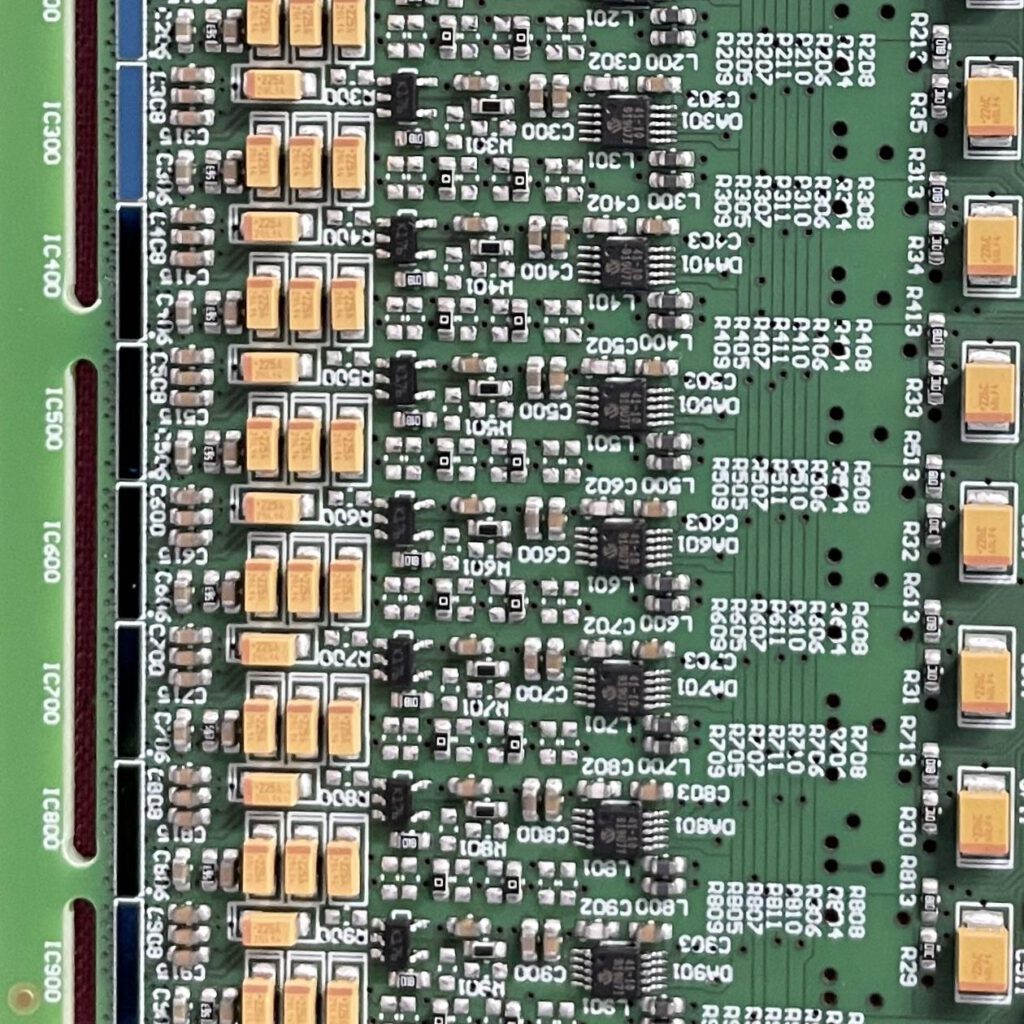
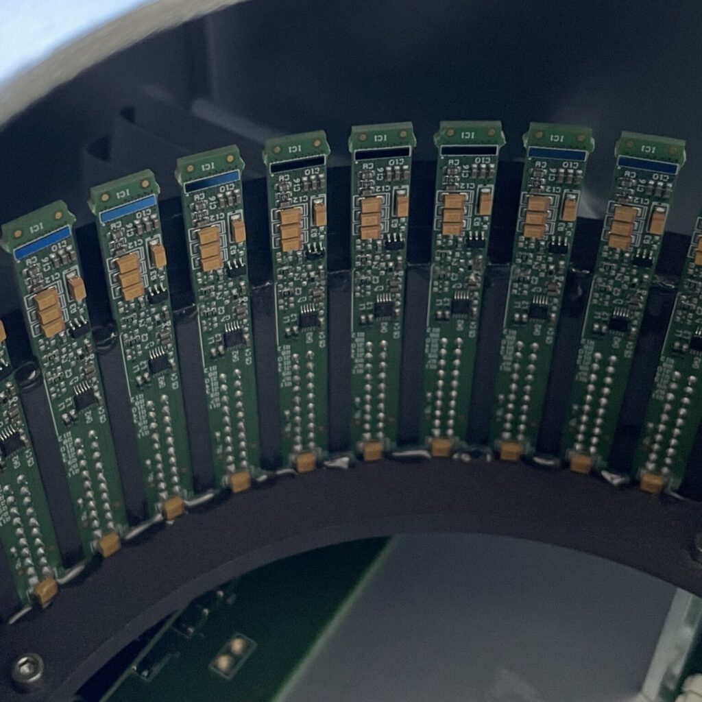
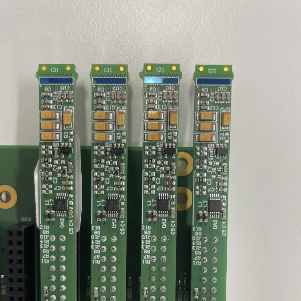
The invention therefore proposes a discontinuous line detector. This detector consists of several individual line detectors or line cameras arranged in one or more spatially offset rows.
The individual detector elements overlap in such a way that one row covers the gaps in the neighbouring row. As a result, the system can continuously detect a shadow boundary even though the detector consists of separate modules.
This modular arrangement can support large measurement widths without requiring one continuous sensor extending across the complete shadow.
How does the system detect the shadow boundaries?
Each individual line detector records an intensity profile across its position. The software identifies the detector regions that show a significant change in light intensity.
These intensity changes indicate the position of the upper or lower shadow boundary. The system then combines the information from the relevant detector elements and calculates the positions of both shadow edges.
By measuring both boundaries, the system can determine the complete shadow width. In addition, the two boundaries provide information that can help identify and compensate for geometric disturbance parameters.
What does calibration-free measurement mean?
For a nearly rotationally symmetrical component, the system can determine the average diameter from measurements recorded over at least one complete rotation of the component. Alternatively, the measurement unit may rotate around the component.
For an ideally rotationally symmetrical body, the method can determine the diameter without requiring a complete rotation within the measurement range.
The patent also explains that using only one shadow boundary for a nearly rotationally symmetrical component may require calibration. By contrast, detecting both boundaries and using the known positions of the light source and detector allows the system to determine additional geometric parameters and support calibration-free radius calculation.
How does the method compensate for rotational errors?
Real rotating systems are rarely perfectly centred. For example, the component may have:
- eccentricity,
- a displaced rotation axis,
- a changing radius,
- mechanical runout,
- displacement of the light source,
- displacement of the detector plane.
The system records the shadow while the component rotates. It can then use the changing positions of the two shadow boundaries to determine disturbance parameters and correct their influence mathematically.
This correction is especially important for nearly rotationally symmetrical components whose radius changes slightly around their circumference.
Advantages over telecentric shadow measurement
Industrial optical diameter measurement often uses telecentric illumination. A telecentric system creates an almost parallel light beam and therefore limits perspective-related changes in the shadow.
However, a telecentric light source for a large component must also be larger than the component diameter. In addition, measuring large or changing diameters may require movement of the light source or detector while maintaining precise parallel alignment.
The patented method instead uses a divergent light beam. According to the patent description, this light source requires less installation space and can be less complex and more economical than large telecentric illumination optics. A single divergent beam can also illuminate components across a wider diameter range.
Advantages for filament winding
The non-contact measurement method offers several potential benefits for filament-winding processes:
- continuous diameter monitoring during production,
- no compression of the wet laminate,
- reduced machine downtime,
- improved repeatability,
- independence from fibre type and layer orientation,
- measurement across changing wall thicknesses,
- digital recording of the manufacturing process,
- earlier detection of dimensional deviations,
- potential integration into process control.
Because the system does not touch the wound component, it can measure wet and mechanically sensitive surfaces without applying an uncontrolled force.
Continuous process control and digital manufacturing
The measured diameter can provide more than a final quality-control value. It can also serve as an input for active process adjustment.
For example, the manufacturing system could respond to a detected diameter deviation by adjusting:
- the quantity of resin,
- the tension of the fibre tape,
- the thickness of the following layer,
- other winding parameters.
The patent description also connects the measurement with continuous process digitalisation, forecasting, control measures and digital-twin concepts. In this way, the measurement system could help correct dimensional deviations while the component is still being produced.
Possible fields of application
The patent describes filament winding as an important application. However, the main claim addresses the measurement of nearly rotationally symmetrical bodies more generally.
Therefore, the concept may also be relevant to other processes involving large or rotating components, for example:
- composite pipes,
- pressure vessels,
- cylindrical tanks,
- wound shafts,
- rollers,
- sleeves,
- tubes,
- rotating semi-finished products.
The suitability for each application would depend on the component geometry, surface conditions, required measurement range and optical installation space. This broader application potential is an inference from the general wording of the patent claim.
Main technical features of the invention
The central technical features include:
- a divergent light beam along the long axis,
- partial collimation along the short axis,
- optical enlargement of the component shadow,
- detection of the upper and lower shadow boundaries,
- a modular discontinuous line-detector arrangement,
- overlapping detector rows for gap-free boundary detection,
- mathematical correction of geometric disturbance parameters,
- average-diameter calculation over a complete rotation,
- non-contact measurement during production.
Together, these features support the continuous optical measurement of components whose size would make conventional shadow imaging difficult or expensive.
Patent citation
Schuller, V.; Rapmund, P.; Schwarz, M.; Schäfer, W. (2024): Method and Device for the Calibration-Free Determination of the Radius of an Almost Rotationally Symmetrical Body Using Shading Technology. German patent publication DE102023110189A1, published 24 October 2024. https://patents.google.com/patent/DE102023110189A1/en
